Gm Accelerator Pedal Position Sensor Wiring Diagram
About press copyright contact us creators advertise developers terms privacy policy & safety how youtube works test new features press copyright contact us creators. Video 17 of 20 in the advanced technology electronic throttle and variable valve control program:
Accelerator Pedal Position Sensor Wiring Diagram Diagram

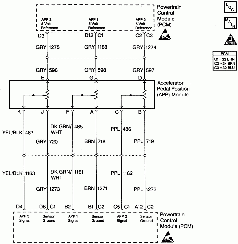
This is the only gm truck system that uses the three app sensors in the accelerator pedal.
/v8-5.0l_sc/Page-474001.png)
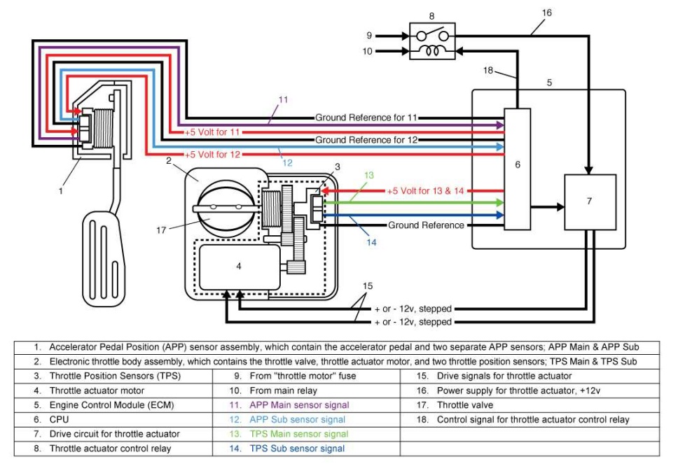
Gm accelerator pedal position sensor wiring diagram. Each one has separate signal, ground, and 5.0 volt reference circuits. With this kind of an illustrative manual, you are going to be able to troubleshoot, stop, and full your projects easily. Buy accelerator pedal position sensor connector 6 wire app for cadillac gmc chevy:
That the accelerator pedal assembly is made up of 3 individual position sensors. Connecting and accessing the signals for the app sensor wi. If you need to test the electronic throttle body itself, check out this tutorial:
With such an illustrative guidebook, you’ll be able to troubleshoot, prevent, and full your assignments with ease. Based on this information the load requested by the driver can be implemented immediately. Each component ought to be set and connected with…
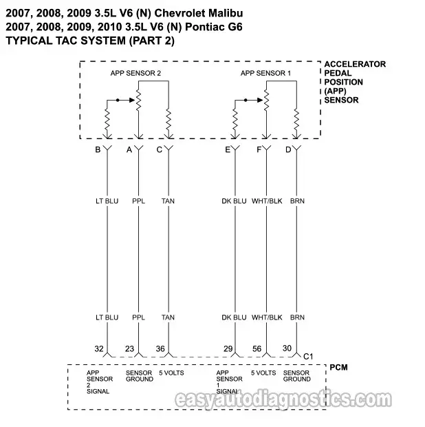
More 3.5l v6 chevy malibu tutorials. Diagnostic trouble code (dtc) p2138 stands for “throttle/pedal position sensor/switch d/e voltage correlation.” it is triggered when the vehicle’s engine control module (ecm) or powertrain control module (pcm) detects that the signals from the two throttle position sensors (or two accelerator pedal position sensors) do not correlate. Accelerator pedal position (app) sensor circuits.
But i need the accelerator pedal position (app) sensor wiring diagram and. Each part ought to be set and connected with different parts in specific way. Open or gnd short in accelerator pedal position main sensor circuit.
Each part ought to be placed and connected with other parts in particular manner. The next step, and the last one of this tutorial, is to check the voltage output of accelerator pedal position (app) sensor 1 with your multimeter in volts dc with the key on and engine off (koeo). Accelerator pedal position sensor wiring diagram wiring diagram is a simplified satisfactory pictorial representation of an electrical circuit it shows the components of the circuit as simplified shapes and the skill and signal links amongst the devices.
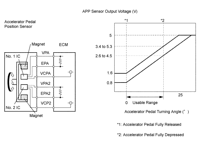
With such an illustrative guidebook, you’ll be able to troubleshoot, prevent, and full your assignments with ease. When the accelerator pedal is at rest (not depressed), it. That app sensor 1's signal increases as the accelerator pedal is depressed, from below 1.1 volt at 0% pedal travel (pedal at rest) to above 2.1 volts at 100% pedal travel (pedal fully depressed).
Later systems use two app sensors. And model year, confirm that all engine to battery and harness to block ground. With such an illustrative guidebook, you’ll be able to troubleshoot, prevent, and full your assignments with ease.
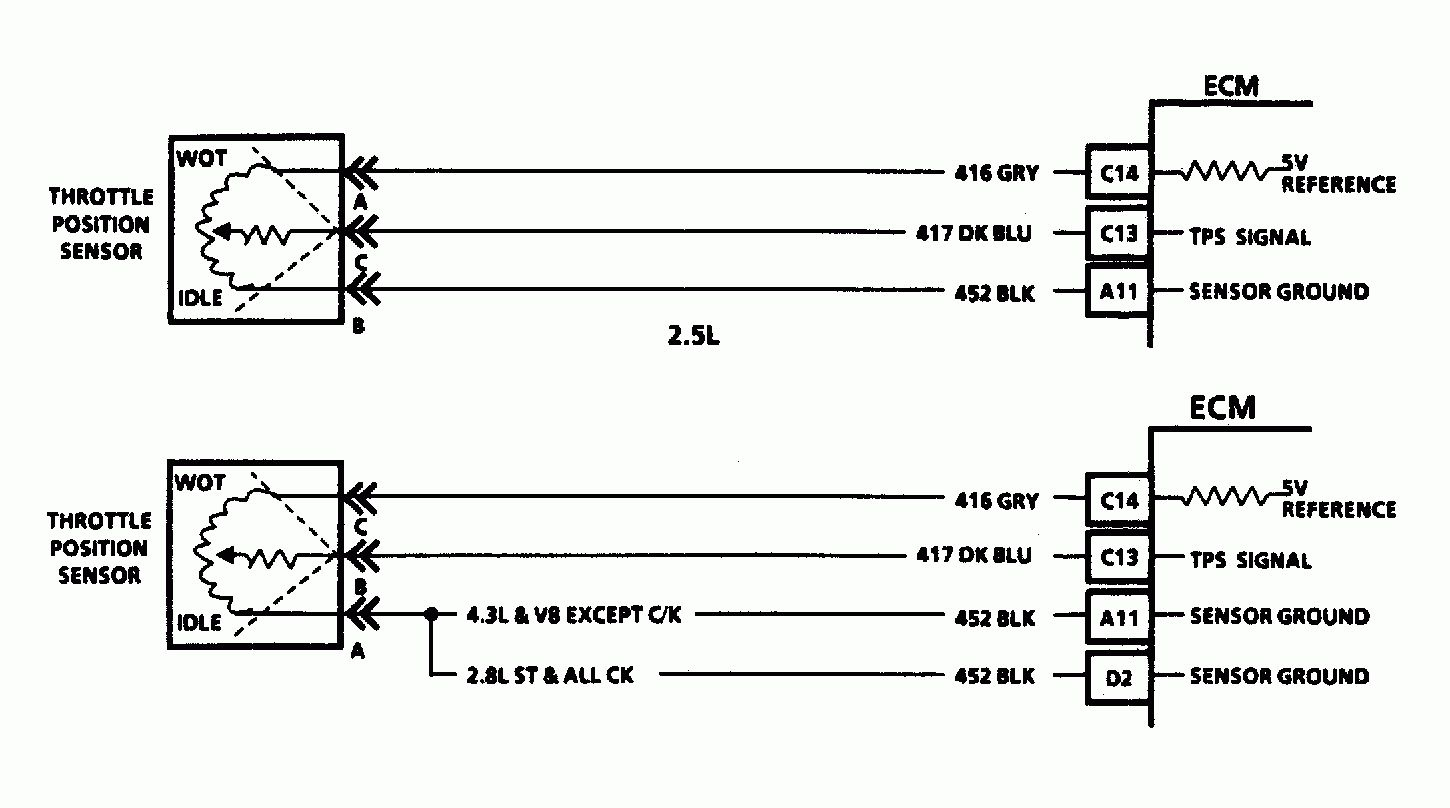
Each component ought to be set and connected with different parts in particular way. Gm is consistent with the wiring colors for their tp sensors: With such an illustrative guide, you will be able to troubleshoot, avoid, and total your tasks without difficulty.
Accelerator Pedal Position Sensor Wiring Diagram Wiring

[GK_3528] Throttle Position Sensor Wiring Diagram Free Diagram
Repair Guides Transmission/transaxle (2002) Automatic


[GK_3528] Throttle Position Sensor Wiring Diagram Free Diagram
Gm Accelerator Pedal Position Sensor Wiring Diagram For
Tps Wiring Harness Wiring Diagram Accelerator Pedal
31 Accelerator Pedal Position Sensor Wiring Diagram

Land Rover Manuals > Range Rover (LM) V85.0L SC
Accelerator Pedal Position Sensor Wiring Diagram Wiring
Repair Guides Diesel Electronic Engine Controls

35 Accelerator Pedal Position Sensor Wiring Diagram Wire

Accelerator Pedal Position Sensor Wiring Diagram Diagram
Gm Body Control Module Wiring Diagram Free Wiring Diagram

My truck is bring up code 22 ( Accelerator pedal position

Throttle position sensor problem?
App Sensor Wiring Diagram Wiring Diagram and Schematic

Gm Ls3 Engine Wiring Diagram Wiring Library
![]()
Accelerator Pedal Position Sensor Wiring Diagram Wiring
Accelerator pedal position (APP) sensor wiring diagram